What Everybody Ought To Know About Why Do MOSFETs Saturate

Solved Problem 1Assuming All MOSFETs Are In Saturation,
Unlocking the Mystery
1. Delving into the Heart of MOSFET Behavior
Ever wondered why a MOSFET, that tiny transistor powering so many gadgets, eventually hits a limit — a point where cranking up the voltage doesn't proportionally increase the current? Well, you're not alone! It's a crucial concept in electronics, and understanding it unlocks a deeper comprehension of how these little workhorses function. In essence, it's all about what happens inside the MOSFET as the gate-source voltage (Vgs) and drain-source voltage (Vds) start playing tug-of-war.
Think of it like this: Imagine a garden hose with a valve. Vgs is like controlling how much you open the valve, letting more or less water (electrons, in the MOSFET's case) flow. Vds is like the water pressure pushing those electrons through the hose. At first, opening the valve wider (increasing Vgs) definitely increases the flow. But, at some point, increasing the water pressure (Vds) doesn't make the flow much faster. The hose is already as open as it can be!
The saturation region is where the MOSFET acts like a current source. It's trying its best to maintain a constant current regardless of how much drain voltage you apply. This region is often used for amplifier circuits, where stable current is essential for consistent amplification. Reaching saturation isn't necessarily a bad thing — it's a characteristic we design around and even exploit in many applications.
So, what actually causes this "hose is as open as it can be" scenario? The key lies in understanding the formation of the channel within the MOSFET. Let's dive a bit deeper into that...
The Channel's Tale
2. The Crucial Role of the Inversion Layer
Remember our garden hose analogy? The "hose" in a MOSFET is the channel — a path of electrons created between the source and drain when a sufficient voltage (Vgs) is applied to the gate. This channel is formed by an "inversion layer," where the type of charge carriers in the semiconductor material near the gate switches (inverts). For example, in an n-channel MOSFET, the region near the gate goes from being p-type to n-type, allowing electrons to flow freely.
As you increase Vds, something interesting begins to happen. The voltage drop along the channel isn't uniform. The voltage difference between the gate and the channel is highest near the source and lowest near the drain. This is because the drain is at a higher potential than the source. So, the inversion layer is strongest near the source and weakest near the drain.
Now, picture this: As you keep cranking up Vds, the voltage difference between the gate and the channel near the drain gets smaller and smaller. Eventually, at a certain Vds value (Vdsat, the saturation voltage), the inversion layer near the drain essentially disappears. This is called "pinch-off." The channel isn't completely gone, but it's severely constricted.
Even though the channel is pinched off, electrons are still flowing from source to drain! They get accelerated across this pinched-off region by the strong electric field, like tiny electrons surfing a wave. But because the channel near the drain is now significantly reduced, further increases in Vds won't lead to a proportional increase in current.
Mathematical Interlude
3. A Glimpse into the Formulas That Govern Saturation
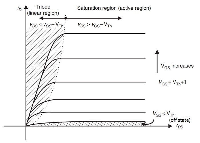
While understanding the physical picture is crucial, a bit of math can really solidify the concept. The saturation voltage (Vdsat) is typically approximated as Vgs - Vt, where Vt is the threshold voltage (the minimum Vgs needed to form a channel in the first place). This is a simplification, but it gives you a good idea of when saturation begins.
The drain current (Id) in the saturation region is approximately given by the equation: Id = (1/2) n Cox (W/L) (Vgs - Vt)^2. Where n is the electron mobility, Cox is the gate oxide capacitance, W is the channel width, and L is the channel length. Notice that Vds doesn't appear in this idealized equation! This reflects the fact that, ideally, the drain current is independent of Vds in saturation.
In reality, the drain current does increase slightly with Vds even in saturation. This is due to an effect called channel-length modulation, which is a fancy way of saying that the effective channel length actually shortens a bit as Vds increases, leading to a small increase in current. This is why the drain current characteristic in the saturation region isn't perfectly flat, but has a slight positive slope.
Understanding these equations is important for circuit designers because they allow us to predict the behavior of MOSFETs in different circuits. By knowing the parameters of the MOSFET (n, Cox, W, L, Vt), we can calculate the drain current for a given Vgs and Vds, and design circuits that perform as expected.

Beyond the Ideal
4. The Imperfections That Shape Reality
So far, we've painted a relatively neat picture of MOSFET saturation. However, real-world MOSFETs are more complicated than our idealized models. Effects like channel-length modulation, velocity saturation (where electrons reach a maximum speed), and temperature dependence can all influence the saturation behavior.
For example, channel-length modulation, as mentioned earlier, makes the drain current increase slightly with Vds even in saturation. Velocity saturation occurs when the electric field in the channel becomes so strong that the electrons can't accelerate any faster. This limits the maximum current that can flow through the MOSFET, even if you increase Vgs.
Temperature also plays a role. As the temperature increases, the electron mobility typically decreases, which reduces the drain current. Furthermore, the threshold voltage (Vt) also decreases with temperature. These effects can complicate the design of circuits that operate over a wide temperature range. That's why temperature compensation circuits are sometimes needed.
These non-ideal effects are especially important to consider in high-frequency and high-power applications. They can affect the gain, bandwidth, and efficiency of amplifiers, and can even lead to device failure if not properly accounted for. Simulations and careful characterization are often necessary to fully understand and mitigate these effects.

Putting it All Together
5. The Bigger Picture in Circuit Design
Why is understanding MOSFET saturation so crucial? Well, it affects how we design circuits! Different regions of operation (cutoff, linear/triode, and saturation) offer distinct characteristics that we can exploit. For example, in amplifier circuits, we typically bias the MOSFET in the saturation region to achieve maximum gain and linearity.
In digital circuits, MOSFETs are used as switches. In this case, we want the MOSFET to be either fully on (conducting with low resistance, operating in the linear region) or fully off (non-conducting, operating in the cutoff region). Saturation is less directly relevant in this application, but understanding the transition between regions is still important.
Moreover, saturation limits the maximum voltage swing in analog circuits. If the drain voltage is pushed too high, the MOSFET will enter the breakdown region, which can damage the device. Therefore, it's essential to choose MOSFETs with appropriate voltage ratings and to design circuits that prevent them from exceeding these ratings.
Ultimately, understanding MOSFET saturation is fundamental to mastering analog and digital circuit design. It allows us to predict circuit behavior, optimize performance, and avoid potential problems. So, keep exploring and experimenting! The world of MOSFETs is vast and fascinating.
Difference Between Mosfet And SSR Forum For Electronics
FAQs
6. Your Burning Questions Answered
Still scratching your head? Here are some common questions about MOSFET saturation:
Q: What is the "keyword term" you used?
A: The keyword term is "Why do MOSFETs saturate." The part of speech of our keyword to be main point is "verb" (saturate)
Q: Is saturation always bad for a MOSFET?
A: Absolutely not! In many applications, especially amplifiers, saturation is the desired mode of operation. It's where the MOSFET provides its highest gain and acts as a current source.
Q: How do I know if a MOSFET is in saturation?
A: A good rule of thumb is to check if Vds > Vgs - Vt. If this condition is met, the MOSFET is likely in saturation. However, remember to consider non-ideal effects like channel-length modulation, which can slightly alter the saturation behavior.
Q: What is the difference between saturation and breakdown?
A: Saturation is a normal operating mode where the drain current becomes relatively independent of the drain voltage. Breakdown, on the other hand, is a failure mode where excessive voltage causes irreversible damage to the MOSFET. Always ensure that the MOSFET operates within its specified voltage ratings to avoid breakdown.